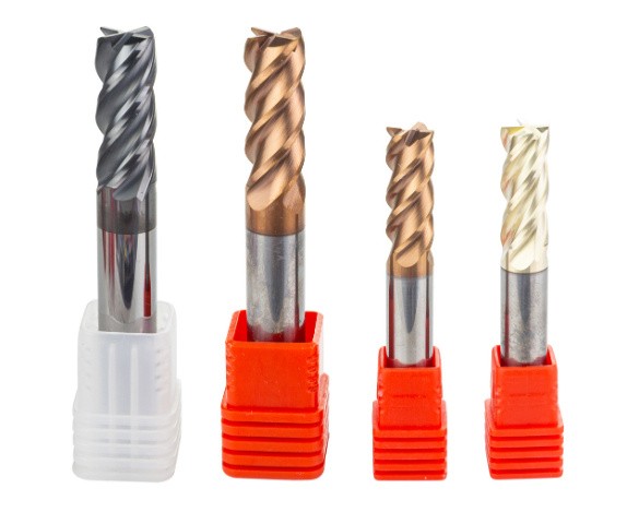
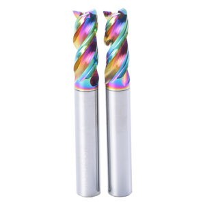
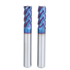
Milling requires running the end mill at the appropriate speeds and feeds; this is by far the most crucial component of the process. In order to facilitate more informed decision-making about the operation of your end mills, we have organized these suggestions into a number of distinct categories. There are several high-performance end mills that have extremely particular operating characteristics in relation to the material families they cut. These have also been included as individual suggestions on the list. These end mills are intended to process a wide variety of materials; but, because to their compact size, feeds and speeds must be carefully tailored to each material. It is important not to overfeed since doing so might result in breaking.
Because these tools have a relatively short length of cut, it is possible to prevent unwanted extension, which is often what leads to deflection and fracture in the material. • They may be used for general-purpose milling including profile, slotting, keyways, and pockets. These end mills are intended to cut tough and abrasive materials, ranging from medium to the greatest hardness levels machinable by end mills.
- The design of the double variable helix cuts down on chatter and harmonics, provides a superior finish, and speeds up the removal of material.
- Rounded corners for increased structural integrity
- Coatings made of AlTiN, Stealth, and Extreme for increased lubricity and increased resistance to heat
- A shank tolerance that is superior than h6 for all shrink fit holders
When it comes to selecting the appropriate parameters to run, the majority of people center their attention on the speed, which is directly related to the machine RPM. This is not correct at all! First ensure that the correct feed per tooth (FPT) is being used, and only then should you alter the speed. When a component is being written and tested out for production, the programmer will often use conservative settings, which will result in chatter. The reason the tool is making such a disturbing noise, known as chatter, is because it is not cutting the material correctly. In most cases, the first line of defense is to reduce the RPM, which will result in the disappearance of the chatter. Although this strategy is successful most of the time, it is not productive. What has just transpired is that the FPT has grown as a result of decreasing the speed while maintaining the feed rate in the same manner. And it’s most probable that the FPT from earlier was already set too low to begin with, which is what led to the talk in the first place.
- On the left side of the chart, choose the material that will be machined into the desired shape.
- Based on the diameter of your mill, choose the appropriate FPT for the material you are working with. The FPT is measured in millimeters per tooth rather than inches per tooth (IPT) (MMPT).
- Determine the radial depth of cut so that you may choose the appropriate chip load factor (CLF).
- Select the appropriate surface feet per minute (SFM) or surface meters per minute in the following: (SMM)
- To determine the RPM of your machine, you will need to know the SFM as well as the diameter of the mill.
- In order to determine the feed rate or IPM, you will need the RPM, the IPT, the CLF, and the number of flutes.
- If you wish to err on the side of caution, choose an SFM that is little lower than what is advised, but always go with the recommended FPT.
Factors Affecting Cutting Speed – Determining Cutting Speed
The pace at which the outer edge of the tool is moving when it is cutting is referred to as the cutting speed. Surface speed is another name for this concept. There is a one-to-one correspondence between surface speed, surface footage, and surface area. The bigger of two tools that are revolving at the same number of revolutions per minute (RPM) has the higher surface speed of the two. The unit of measurement for surface speed is the surface foot per minute (SFM). The surface footage concept underlies the operation of any cutting instrument. The kind of material being cut and the type of cutting tool being used are the two primary factors that determine the cutting speed. When determining the optimal cutting speed, the level of toughness of the material being cut into plays a significant role. The more difficult the material being cut, the slower the cutting speed will be.
Feed Rate Determination – How to Choose a Feed Rate
The speed at which the lead screw or feed rod is turning is what determines the feed rate of an end mill. The quick-change gearbox’s changing gears are responsible for controlling the vehicle’s speed. When doing a rough cut, the objective is to simply eliminate any surplus material from the stock; hence, a coarse feed should be used. When completing a cut, it’s necessary to have a nice surface finish, and because the process has to finish the size of the machining components, using a fine feed is something that needs to be done. When doing ordinary CNC turning with an HSS cutting tool, it is advised that the roughing feed rate be between.005 and.020 inches per revolution, while the finishing feed rate be between.002 and.004 inches per revolution. When referring to a milling machine, the term “feed” refers to the rate, measured in inches per minute, at which the workpiece advances toward the cutter. The milling machines that LBCC has feature feed systems that are separate from the spindle speeds of the machines. This configuration works well and enables quicker feeds to be used with cutters that have a slower rotational speed.
The feed rate that is used by a milling machine is determined by a number of parameters including the following:
- The depth and breadth of cut
- The kind of cutter that was used.
- The degree of sharpness possessed by the cutter
- The substance that makes up the workpiece.
- The needed accuracy, finish, and uniformity of the workpiece;
- The required level of finish;
- The required level of accuracy
The strength and stiffness of the machine, as well as the holding device and the tooling configuration.
Cutting Depth
The distance that the end mill penetrates into the material is referred to as the depth of cut. a common unit of measurement is in millimeters or thousandths of an inch. When rough cutting stainless steel, for example, you might use a feed rate of 0.020 inches per revolution and a depth of cut of 0.100 inches. This would result in a diameter reduction of 0.200 inches. General machine practice recommends using a depth of cut that is up to five times greater than the rate of feed. If chatter marks or increased machine noise are seen, the depth of cut should be decreased.
It refers to the overall quantity of metal that is sliced away with each pass of the cutting tool. It is written out using millimeters. It may change and be contingent on the kind of tool and the substance being worked on. According to the formula, it is equal to half of the difference between the diameters.
End Mill For Aluminum
Aluminum is one of the materials that is machined the most often since most forms of the material have good machinability. As a result, aluminum is one of the materials that is most frequently utilized in manufacturing. Because of this, there is often a lot of rivalry in the market for aluminum machining. Machinists may get a competitive edge in their field by mastering sophisticated milling procedures for aluminum as well as the fundamentals of tool selection, operating parameters, and other milling processes. The performance of highly balanced machining centers, which are able to run at higher RPMs and feed rates, is optimized for the use of high balance end mills, which are intended to greatly boost that performance. These cutting tools have been particularly designed with a fine balance for high-velocity machining in aluminum (up to 33,000 RPM). Even at high speeds and high depths of cut, the sweet spot won’t be present in every single aluminum milling operation. This is true even when the speeds and depths of cut are increased. There are at least three circumstances in which it is possible that it is not essential to look for a sweet spot.
| Processed material | Aluminum alloy | Silicon aluminum alloy Si≤10% |
||
| Diameter(mm) | Rotating speed(min-1) | Feed rate(mm/min) | Rotating speed(min-1) | Feed rate(mm/min) |
| 1 | 40000 | 800 | 40000 | 600 |
| 2 | 40000 | 1200 | 32000 | 900 |
| 3 | 26500 | 1800 | 21000 | 1300 |
| 4 | 20000 | 2000 | 16000 | 1500 |
| 5 | 16000 | 1750 | 13000 | 1300 |
| 6 | 13000 | 1500 | 10600 | 1200 |
| 8 | 10000 | 1650 | 8000 | 1300 |
| 10 | 8000 | 1900 | 6500 | 1500 |
| 12 | 6600 | 1950 | 6300 | 1550 |
| 14 | 5700 | 2000 | 4600 | 1600 |
| 16 | 5000 | 2000 | 4000 | 1600 |
| 18 | 4400 | 2000 | 3500 | 1600 |
| 20 | 4000 | 2000 | 3200 | 1600 |
End Mill For Steel
Steel can be machined and is a material that can be found in almost any kind of machine shop. Determine the milling operation’s end mill for steel cutting speed and feed rate, as well as the cut time for a specific cut length, before beginning the milling process. In milling operations, a workpiece is fed into a spinning cutting tool that has sharp teeth, such as an end mill for steel. This causes the removal of material from the workpiece. Calculations for end mills for steel employ the required tool diameter, number of teeth, cutting speed, and cutting feed. These parameters should be set based on the unique cutting circumstances, which include the material of the work piece and the material of the tool. When milling steel, the feeds and speeds will be all over the place since it depends on the grade of steel, the material of the tool, the depth and breadth of the cuts, the number of flutes, and so on.
| Processed material | Cast iron/Ductile Iron | Carbon Steel/Alloy Steel ~750N/mm2 | Carbon steel, Alloy steel ~30HRC | Pre-hardened steel,Quenched and tempered steel ~40HRC | Pre-hardened steel,Quenched and tempered steel ~50HRC | |||||
| Diameter(mm) | Rotating speed(min-1) | Feed rate(mm/min) | Rotating speed(min-1) | Feed rate(mm/min) | Rotating speed(min-1) | Feed rate(mm/min) | Rotating speed(min-1) | Feed rate(mm/min) | Rotating speed(min-1) | Feed rate(mm/min) |
| 1 | 20000 | 225 | 20000 | 225 | 20000 | 180 | 20000 | 180 | 20000 | 135 |
| 2 | 15000 | 360 | 15000 | 360 | 15000 | 325 | 15000 | 315 | 13000 | 200 |
| 3 | 14000 | 610 | 14000 | 610 | 13000 | 570 | 10600 | 470 | 8500 | 370 |
| 4 | 10800 | 630 | 10800 | 630 | 10000 | 575 | 8000 | 480 | 6500 | 380 |
| 5 | 8200 | 660 | 8200 | 660 | 7600 | 600 | 6400 | 505 | 5000 | 400 |
| 6 | 7000 | 675 | 7000 | 675 | 6400 | 620 | 5300 | 515 | 4200 | 405 |
| 8 | 5200 | 665 | 5200 | 665 | 4800 | 610 | 4000 | 510 | 3200 | 415 |
| 10 | 4200 | 660 | 4200 | 660 | 3800 | 600 | 3200 | 505 | 2500 | 390 |
| 12 | 3500 | 660 | 3500 | 660 | 3200 | 600 | 2650 | 505 | 2100 | 390 |
| 14 | 3000 | 610 | 3000 | 610 | 2700 | 570 | 2300 | 470 | 1800 | 370 |
| 16 | 2600 | 610 | 2600 | 610 | 2400 | 570 | 2000 | 470 | 1600 | 370 |
| 18 | 2300 | 600 | 2300 | 600 | 2100 | 560 | 1800 | 460 | 1400 | 365 |
| 20 | 2050 | 600 | 2050 | 600 | 1900 | 560 | 1600 | 460 | 1250 | 365 |
End Mill For Stainless Steel
When compared to carbon and low-alloy steels, the level of corrosion resistance offered by stainless steels is much higher. This is primarily attributable to the high amount of chromium that is included in stainless steel alloys, with the majority of grades possessing at least 10% of the element. Milling steel, on the other hand, may be a very challenging process. Because stainless steels are infamous for being “end mill killers,” it is vital to dial in your speeds and feeds and use the appropriate tool in order to achieve success in machining. In order to achieve more efficient machining, one of the most crucial steps is choosing the appropriate tools, but another is finding the optimal operating settings. The running parameters for machining stainless steel are determined by a number of different elements, however there are certain fundamental recommendations that may be followed as a starting point.
When machining stainless steels, it is generally advised to use an SFM of between 100 and 350, and the chip load should range from. 0005″ for a 1/8″ end mill up to. 006″ for a 1″ end mill…
| Cutting amount (mm) | ap≤1D | VC m/min |
| ae≤0.1D | 100 (80-120) | |
| Processed material | Stainless steel (Side milling) | |
| Diameter(mm) | Rotating speed(min-1) | Feed rate(mm/min) |
| 1 | 25000 | 700 |
| 2 | 15900 | 635 |
| 4 | 7960 | 700 |
| 6 | 5300 | 680 |
| 8 | 3980 | 730 |
| 10 | 3180 | 660 |
| 12 | 2650 | 600 |
| 16 | 1990 | 490 |
| 20 | 1590 | 460 |
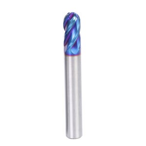
Ball Nose End Mill
When milling curved surfaces, slotting, and pocketing, ball end mills, which are also known as ball nose end mills, are the tools of choice. In the process of manufacturing molds, a tool called a ball end mill with a circular cutting edge is often used. The machining of three-dimensional contour forms, such as those generally found in the production of turbine blades, and the fulfilment of general component radius requirements are all appropriate applications for ball nose end mills. The Effective Cutting Diameter (Deff) of a ball nose end mill is not the same as its actual cutting diameter when the Axial Depth of Cut (ADOC) is less than the whole radius of the ball.
| Processed material | Cast iron/Ductile Iron | Carbon Steel/Alloy Steel ~750N/mm2 | Carbon steel, Alloy steel ~30HRC | Pre-hardened steel,Quenched and tempered steel ~40HRC | Pre-hardened steel,Quenched and tempered steel ~50HRC | |||||
| Diameter(mm) | Rotating speed(min-1) | Feed rate(mm/min) | Rotating speed(min-1) | Feed rate(mm/min) | Rotating speed(min-1) | Feed rate(mm/min) | Rotating speed(min-1) | Feed rate(mm/min) | Rotating speed(min-1) | Feed rate(mm/min) |
| R0.5 | 40000 | 800 | 40000 | 800 | 38000 | 700 | 32000 | 320 | 25000 | 275 |
| R1.0 | 24000 | 900 | 24000 | 900 | 19000 | 760 | 16000 | 400 | 13000 | 275 |
| R1.5 | 15500 | 950 | 15500 | 950 | 12750 | 760 | 10600 | 450 | 8500 | 280 |
| R2.0 | 11500 | 950 | 11500 | 950 | 9550 | 760 | 8000 | 550 | 6500 | 370 |
| R2.5 | 9500 | 1050 | 9500 | 1050 | 7650 | 800 | 6400 | 550 | 5000 | 375 |
| R3.0 | 8000 | 1050 | 8000 | 1050 | 6400 | 800 | 5300 | 580 | 4200 | 390 |
| R4.0 | 6000 | 1300 | 6000 | 1300 | 4800 | 950 | 4000 | 700 | 3200 | 440 |
| R5.0 | 4800 | 1200 | 4800 | 1200 | 3800 | 900 | 3200 | 650 | 2500 | 440 |
| R6.0 | 4000 | 1100 | 4000 | 1100 | 3200 | 840 | 2650 | 610 | 2100 | 420 |
| R8.0 | 3000 | 1050 | 3000 | 1050 | 2400 | 800 | 2000 | 600 | 1600 | 375 |
| R10.0 | 2400 | 950 | 2400 | 950 | 1900 | 680 | 1600 | 560 | 1250 | 330 |
Conclusion
The process of determining the correct speeds and feeds for your end mill may be a hard one. However, it is essential to have a grasp of the optimal feeds and speeds before you begin operating your machine in order to guarantee that your end mill will last as long as it should. When an end mill is run at a speed that is too high for it, the chip size produced may not be ideal, and the end mill may even break. On the other hand, a low RPM might lead to deflection, a poor finish, or simply lower rates of metal removal. Contact the HUANA tools if you are confused what the optimal feeds and speeds are for the task that you are working on.


