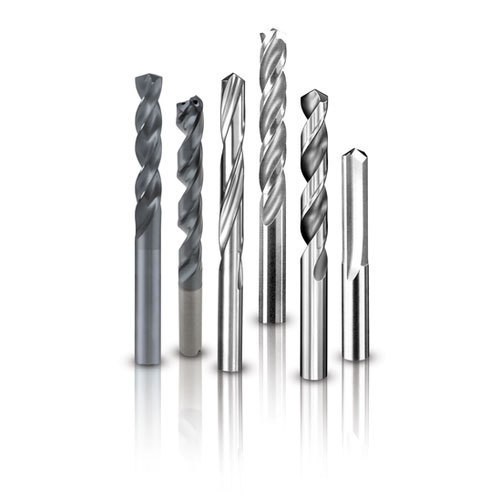
What is a carbide drill?
An extra tough and durable carbide coating is applied to the tip of the extra-long carbide drills bit, coating it with a combination of high carbon steel and carbide. Using the coating to the carbide drill bit will allow it to drill a hole in masonry, rock, and very tough steel without burning it up due to the tremendous amount of heat it generates during the drilling process.
You can’t drill without drill bits, just as you can’t saw without blades. Each material requires a unique type of bit. Drilling metal, masonry, and wood are easy with specially designed bits. By using bits with diamond or tungsten carbide tips, you can cut through glass or tiles without breaking them. As with any extra-long carbide drills bit, the quality of the bit is determined by the material used to manufacture it. This material, in turn, is what determines their ability to drill into different types of materials. Various combinations of carbide, titanium, cobalt, etc., are often used with high-speed steel (HSS) as the material for drill bits. Most often, it is combined with titanium, cobalt, etc.
Type of Carbide Drill Bits
Twist drill
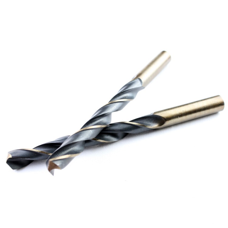
In general, twist drills are the most commonly used hole machining tools for drilling holes. The diameters of these pipes range from about 0.25 to 80 mm, depending on what type they are.
The drill bit comprises two primary parts: the working part and the handle. This part of the tool has two spiral grooves similar to twists on the functional aspect. An inverted cone shape twist drill reduces friction between the guiding portion and the hole’s wall during drilling by gradually decreasing its diameter from handle to shank.
There is a close relationship between the helix angle of the twist drill and the size of the rake angle on the cutting edge, the strength of the blade, and chip removal. The helix angle of the twist drill is generally 25° to 32°. In addition, the front end of the drill bit is sharpened to form a cutting portion, and the spiral groove can be machined by milling, grinding hot rolling, or hot extrusion. Cutting edge angles on twist drills range from 118 degrees to 118 degrees, blade bevel angles range from 40° to 60°, and relief angles range from 8° to 20°. During drilling, the rake angle becomes negative (up to -55°) at the rake edge due to structural reasons. It would help if you considered a reliable carbide drill bits supplier.
Cutting portions of twist drills can be ground into different shapes according to the material being processed to improve their cutting performance. Straight shank and taper shank are the two types of handles for twist drills. While the former is clamped in the drill chuck, the latter is used to drill a tapered hole for the tailstock or machine spindle. Twist drills are made of high-speed steel. In addition, to cast iron and steel, carbide inserts or crowns can be used with twist drills to machine non-metallic materials. With solid carbide, small twist drills, printed circuit boards, and instrument parts are processed.
Flat drill

Simple structure and low craft costs make the flat drill a good choice. The machined hole has a spade-shaped cutting area, which makes it easier for the cutting fluid to get into. There can be no doubt about the fact that flat drills perform poorly in terms of cutting and chip expulsion. In addition to integral drills, we also offer assembled ones available for purchase. As mentioned earlier, the monolith is mainly used for micro-drilling holes between 0.03 and 0.5 mm. To drill large holes with a diameter ranging from 25 to 500 mm, and if necessary, for internal cooling, the flat drill blade attached to the assembly is interchangeable and can be cooled internally.
Deep hole drill

Drilling a deep hole with a deep hole ratio of greater than six usually refers to a tool that uses a depth-to-hole ratio greater than 6 for drilling holes. Among deep hole drills, gun drills, BTA drills, jet drills, and deep hole DP drills are the most common.
Broaching drill
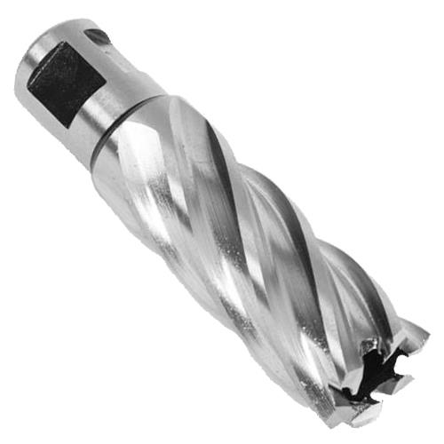
Drills designed for reaming have three to four teeth and are more rigid than twist drills to provide an excellent level of machining accuracy and finish to holes that have already been drilled.
Countersink drill
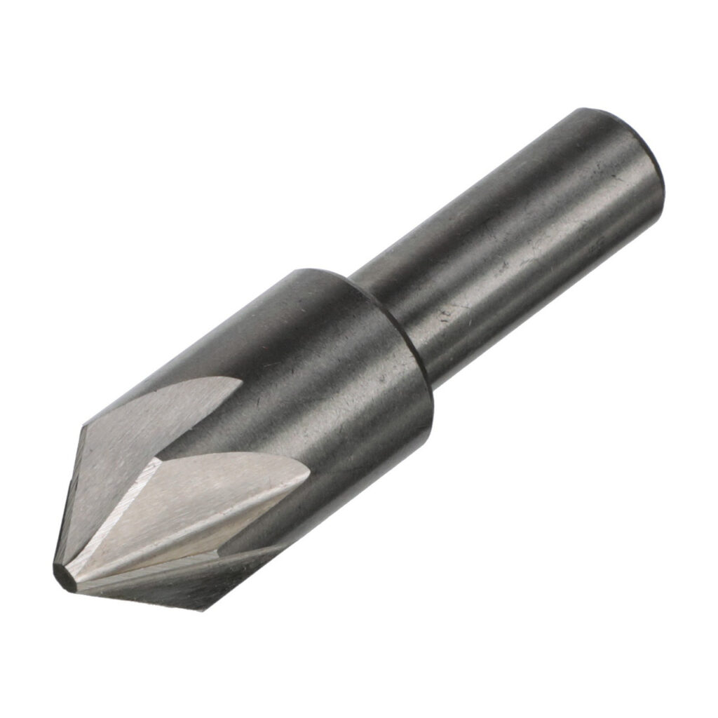
Countersink drills have many teeth, and their hole ends are formed through a method that flattens the outer surface of the holes or processes the countersunk holes of various countersunk screws.
Center drill
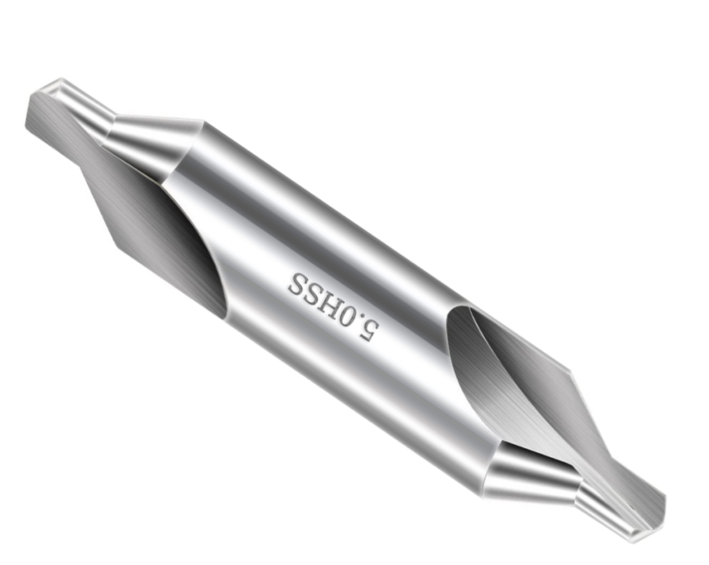
Drilling holes at the center of the shaft workpiece is, in fact, the main function of the center drill. Compound center drills combine twist drilling with boring drilling, also called composite center drills.
Common Drill Angles
118° and 135° are the most commonly included angles for drills. Traditionally, drill bits were conventional conical shaped, so these angles result from manual drilling. As tool makers learned over time, grinding a conical point with a flat surface (a facet) could reduce the thrust required to cut metal and wood while also improving the process of chip removal and metal or wood removal. This is a major advantage if you are drilling by hand. This is a major advantage if you are drilling by hand.
With the advancement of drilling machines, multifaceted drill points are becoming more commonplace. The drill points produce 60% less heat than conventional drill points and consume 50% less energy than traditional ones. Each configuration is suitable for a specific job when combined with a particular point of drill angle.
The drill points on jobber drills are typically angled at 118° to facilitate general drilling applications. The 135° variation on these machines is designed to take advantage of the variation between hard and soft metals and is typically used to cut aluminum and stainless steel. With its flatter surface than 118°, 135° drills have more cutting lips that contact the material surface sooner to initiate full metal cutting. 118° and 135° drill points are available in various configurations. Drilling applications dictate the configurations to be used.
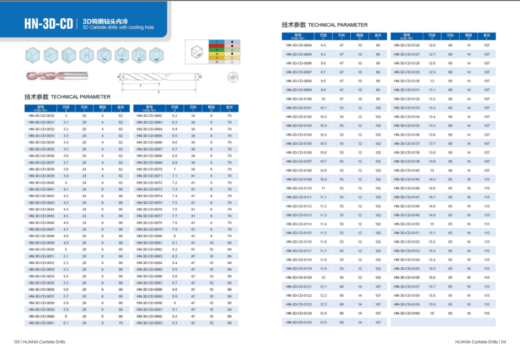

Drill Feed and Speed
To achieve good CNC cuts, selecting the right cutting speed (feed rate) and the right router/spindle RPM is important. Before deviating from recommended settings, it is important to understand feeds and speeds fully.
Chip load, which represents what size chips are produced during the cutting process, is one of the most important concerns of machining. Getting the maximum amount of chip load is critical to improving productivity, reducing the heat created, and preventing premature cutter tips dull. In the case of a low chip load, bits will become too hot and dull more quickly. Too high a chip load may cause the bit to chip or break. Too much chip load will cause the tool to deflect, leading to poor surface finish. Feed rate, RPM, and flute number are all factors that affect chip load. Cutter’s teeth take chunks of material as they rotate. A cutter’s speed depends on the rate at which it moves forward and turns in the material. Any cutting situation can be determined using this formula.
As a starting point, these numbers are a good place to start, but they will need to be adjusted to account for the actual conditions encountered in the field. It is necessary to record router settings as they will work for similar cuts in similar materials even if the router runs lower than the setting on the router indicates. To ensure it falls within an acceptable range, it is recommended to start with low numbers. A particular cutting or machining operation will require testing in this range of parameters since there is considerable overlap.
Optimizing feed rates and speeds
By selecting the chip load, you should start by determining the RPM for the material being cut.
As the part’s finish quality deteriorates or moves away from hold downs, increase the cutting speed (feed rate). Reduce speed by 10%.
If the finish deteriorates, reduce RPM until acceptable, then increase RPM until it is again permitted.
For maximum chip removal, RPM and speed are optimized. Different feeds and speeds are available to start at to reduce the amount of work needed. Feeds and speeds can be optimized to boost performance. You should adjust the surface finish if there are any problems with the finish. To ensure the hold-down method is adequate, it may be necessary to revisit it if there are a lot of work holding issues.
Choosing a drill bit
You must first decide what type of metal you would like to drill to select the right metal drill bit.
The hardness and resistance to the drilling of all metals depend not only on their weight but also on their density. Some metals are heavier than others, such as lead and aluminum. However, aluminum is slightly harder than lead. Extra long carbide drills must have a harder surface than the metal intended to drill due to the metal’s density. An iron-carbon alloy won’t be scratched by a drill bit that can easily bore a hole in aluminum.
Metal drill bits are composed of diverse materials and elements to enhance cutting ability and hardness. Metal drill bits can be divided into two categories:
- The steel used in high-speed applications (HSS) is alloy steel (an alloy containing a metallic element and a chemical component to give the steel its unique feature.
- Hard metal or carbide is a solid created by heating powdered carbide tungsten with binding elements like titanium or cobalt.
In drilling metal, what is the cutting speed of the drill bit?
It would help if you considered the following factors when drilling metal, as they will influence drilling speed and feed:
- Drilling metal.
The hardness of the metal and how it reacts to drilling can be determined by identifying the metal that will be drilled.
- A metal’s hardness.
Drilling at a slower speed is required for harder metals.
- Utilization of cutting fluids.
For drilling metal, a cutting paste or compound should be used. The cutting process will be easier when cutting fluid is used, allowing for faster cutting speeds.
- Use of a particular drill bit.
Each type of drill bit will have a different speed rating and is available in various sizes.
- Drilling hole diameter.
Drilling a larger hole will result in a larger surface area where metal will be in contact, resulting in a faster heat buildup. Feed rates slow down as hole diameter increases.
- Drilling depth.
Drilling a hole larger than twice its diameter requires reducing the drill bit speed to prevent heat buildup from accelerating.
- Hand drills or pedestal drills.
Drill bits will be more accurately positioned if you use a pedestal drill. The feed rate and speed can be adjusted accordingly. The feed rate and speed can be adjusted accordingly.
Drill Bit Sizes
International standards also define Drill Bit Sizes, just as they do for other gauges. Drill bit sizes in fractional inches and wire gauges are prominent in the United States, while they are more prevalent in the rest of the world.
Fractional drill bits are specified in ANSI B94.11M-1979 and range from 1/64 inch to 1 inch.
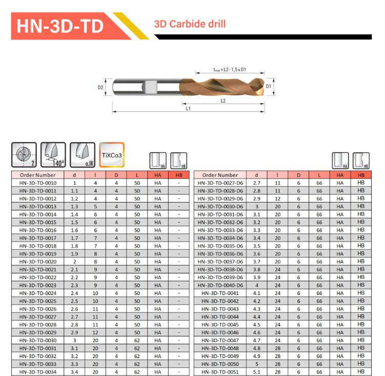
There are several ways in which the drill size can be represented in metric; the drill size is matched up to the diameter of the drill size.
Bottom Line
In a Drill, the Drill Bits are the main part responsible for making holes. The type of drill bit that is needed for different materials varies. In terms of Drill Bit Sizes, these are the diameters and the lengths of the holes we would like to drill. They are described as gauge numbers, fractional inches, or just simple millimeters based on the diameter of the hole. For drilling holes, we need to be aware of two types of drill bit sizes that are important to know: drill bit diameter and drill bit length. The drill bit diameter is the size of the drill bit. Depending on the diameter of the hole, the gauge number will be expressed as a fractional inch, millimeter, or just a simple gauge number that will indicate the gauge of the hole. We learned the importance, types of drill bits, and standards associated with drill sizes. Taking care of your bits is essential for whichever kind of bit you choose. Additionally, make sure to select the right carbide drill bits supplier.

