About the classification of tools
hole processing tools
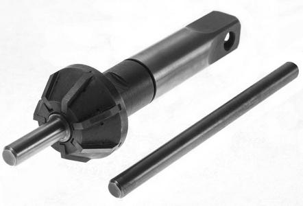
In machining processes, hole processing tools are a crucial part of mechanical machining, including drills, hole enlarging drills, boring tools, reamers, and internal surface pull knives. Compared to other machining methods, hole boring is considered a more challenging process. It relies solely on adjusting a single blade (or blade holder) to machine micrometer-level holes, such as H7 or H6.
boring tools
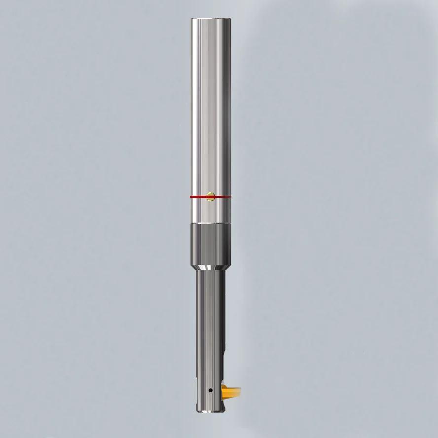
A boring tool is a type of cutting tool used for boring, commonly employed in internal hole machining, hole enlargement, and internal contour imitation. It consists of one or two cutting parts, specifically designed for the rough, semi-finish, or finish processing of existing holes. Boring tools can be utilized on boring machines, lathes, or milling machines.
a single flute boring tool
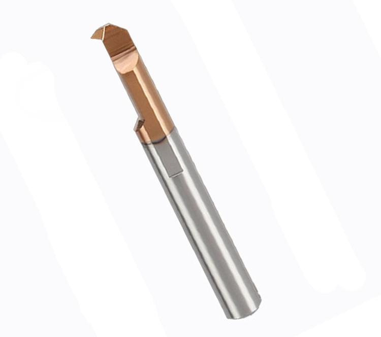
The shape of the cutting part of a single flute boring tool is similar to that of a lathe tool. To achieve high dimensional accuracy for the hole, a fine adjustment boring tool can precisely adjust the bore size on the machine tool.
It has a dial with a precise scale line, and the dial, along with the spindle containing the boring head, forms a pair of precision lead screw nut mechanisms. When the nut is rotated, the spindle with the tool head can move in a straight line along the directional key. With the precision of the scale readings, the accuracy can reach 0.001 millimeters.
Two flute boring tools
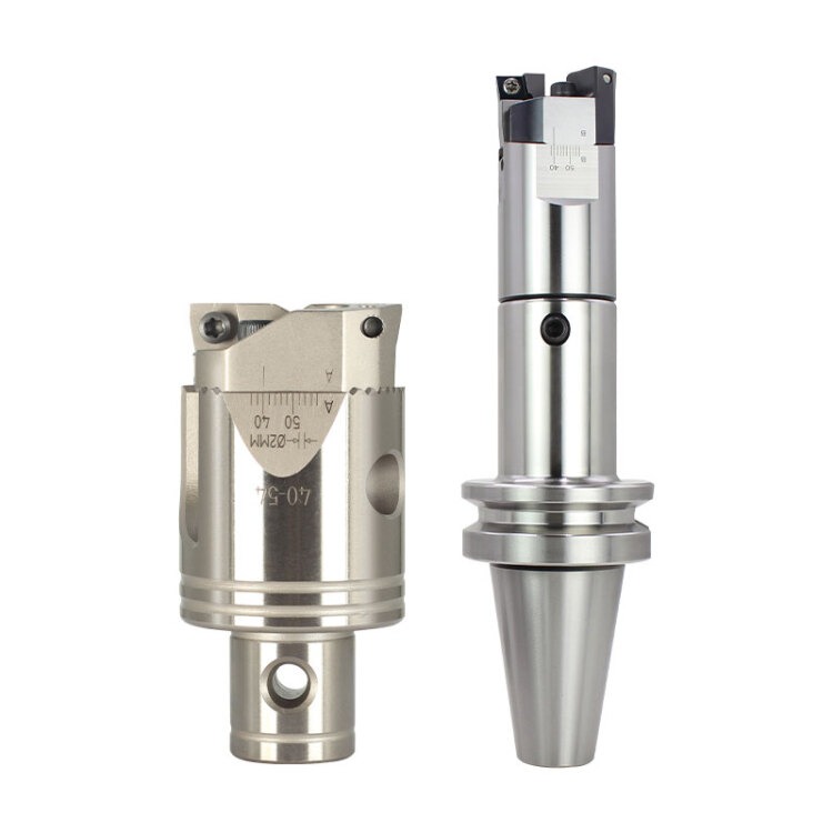
Two flute boring tools have two teeth distributed on both sides of the center, cutting simultaneously. Due to the balanced radial forces generated during cutting, it can increase the cutting amount, resulting in high production efficiency. Double-edge boring tools are classified into floating boring tools and fixed boring tools based on whether the floats on the boring bar.
Floating boring tools are suitable for precision machining of holes. In essence, they are similar to reamers and can bore holes with high dimensional accuracy and smooth surfaces.
Features
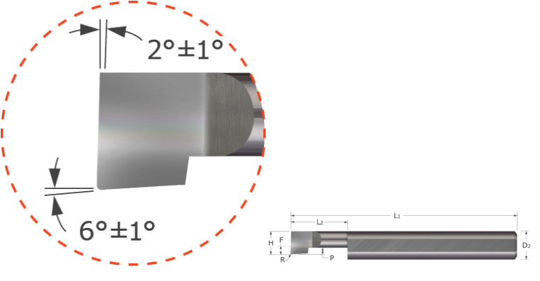
- Designed for facing and boring applications in bores .0550″ and larger
- Polished split face for improved edge retention and chip evacuation while reducing galling
- Split geometry makes the tool as rigid as possible
- Corner radius profile
- Lockdown flat automatically locates tool on center
- Coating options provide added lubricity and increasedwear resistance in difficult to machine materials
- Solid carbide• CNC ground in the USA
How to choose right boring tools?
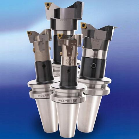
Tool Rotation
When processing at the machining center, the tool rotates. The boring tool has a fine adjustment mechanism or automatic compensation function, allowing for micron-level adjustments according to tolerance requirements.
Due to the continuous change in the direction of chip flow, cooling of the tool tip, workpiece, and chip discharge are more challenging compared to lathe machining.
Tool Vibration
- Rigidity Impact of the Tool System: This includes the rigidity of the tool holder, boring bar, and the intermediate connecting part. Rigidity of the tool system is especially crucial for machining small holes, deep holes, and hard materials, particularly in cantilevered machining.
- Dynamic Balance Impact of the Tool System: In relation to the rotation axis of the tool system, any imbalance in the tool’s mass can lead to vibration due to centrifugal force during rotation. This effect is particularly significant during high-speed machining.
- Workpiece Inherent or Fixed Rigidity: Some smaller, thinner components lack sufficient inherent rigidity, or due to factors like the shape of the workpiece, cannot be adequately secured using reasonable fixtures.
- Influence of Blade Tip Shape: Different cutting resistances are generated based on variations in the front angle, tip radius, and chip-breaking groove shape of the blade.
- Effects of Cutting Conditions: This includes cutting speed, feed rate, depth of cut, as well as the method and type of cutting oil application.
- Impact of the Machine’s Spindle System: Factors such as the rigidity of the machine spindle itself, the performance of bearings and gears, and the connection rigidity between the spindle and tool holder.
properly clamp the tool
Tool Clamping When boring holes, it is crucial to properly clamp the tool. The center height of the tool is a significant factor leading to tool failure.
- When the cutting edge relative to the main and back angles of the workpiece decreases, the tool’s back face contacts the workpiece, causing friction between the blade and the workpiece. As the blade rotates, this friction further causes the blade tip to deviate, leading to deeper cutting into the workpiece. Increasing the front angle can reduce plastic deformation of the front face squeezing the cutting layer, decreasing friction resistance as chips flow through, thereby reducing cutting forces and heat. However, increasing the front angle will simultaneously lower the strength of the cutting edge, reducing the heat dissipation volume of the tool head.
- When the tool’s back angle decreases, the front angle of the blade relative to the workpiece increases, causing the tool to scrape the workpiece. This situation is more severe when boring small holes. Therefore, tool installation should be slightly higher than the center height (but as close as possible to the center height). This allows the tool’s normal back angle to increase, improving cutting conditions. If vibration occurs during processing, the tool tip will deflect downward and toward the center, approaching the ideal center height. The tool can also slightly retract, reducing the likelihood of damaging the workpiece. A smaller front angle stabilizes working pressure. If the front angle is reduced to 0°, excessive working pressure can lead to tool failure, so a boring tool with a positive front angle should be selected. Chip Disposal During machining, due to the tool being inside the hole, cutting fluid is challenging to reach the cutting edge, causing difficulty in chip disposal and affecting the tool’s lifespan.
diameter and length
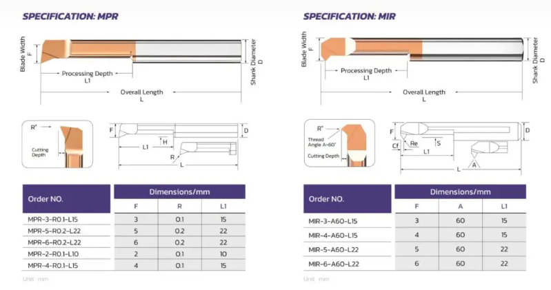
The selection of boring tools is greatly restricted by the part’s hole diameter and length (depth and overhang).
- The general principle is to choose the shortest overhang and the largest possible tool size. Selecting the right tool, applying it correctly, and reliably clamping it can minimize tool deflection and vibration.
- When the tool is cutting, both tangential cutting force and radial cutting force attempt to deviate the tool from the workpiece. Any radial deflection means a decrease in cutting depth and chip thickness, leading to vibration tendencies. Radial deflection affects the processed hole diameter, while tangential deflection means the blade’s cutting edge moves downward, deviating from the centerline. Factors to consider during boring include: blade groove shape, chip evacuation issues, and tool requirements.
- The primary clearance angle of boring tools influences the direction and magnitude of axial and radial forces. The tool tip radius and tip angle are crucial for reducing radial and tangential forces. An empirical guideline is that the tip radius should be slightly smaller than the cutting depth. In internal hole turning, it’s preferable to use tools with a basic shape of a positive front angle, which generates lower cutting forces than tools with a negative front angle. Choosing materials with a low friction coefficient, such as metal ceramic blades, thin-coated blades, or non-coated blades, generally results in lower cutting forces and should be preferred.
- In the process of internal hole machining, chip evacuation is crucial for performance and safety. Short chips consume higher power during processing, increase vibration, and cause crescent moon wear on the blade. Longer chips lead to chip evacuation problems. Short, helical chips are ideal for cutting as they are easier to evacuate, exerting less pressure on the cutting edge during chip breaking.
- Centrifugal force compels chips to move outward; usually, chips remain inside the hole, and the tool compresses them onto the machined surface, potentially damaging parts and tools. Therefore, measures should be taken to improve chip evacuation performance: using internal cutting fluid helps with chip evacuation, or using compressed air to blow chips out through the spindle via through-holes. Inverted boring helps keep chips away from the cutting edge. Lowering cutting speed and using small cutting heads maximize chip clearance space.
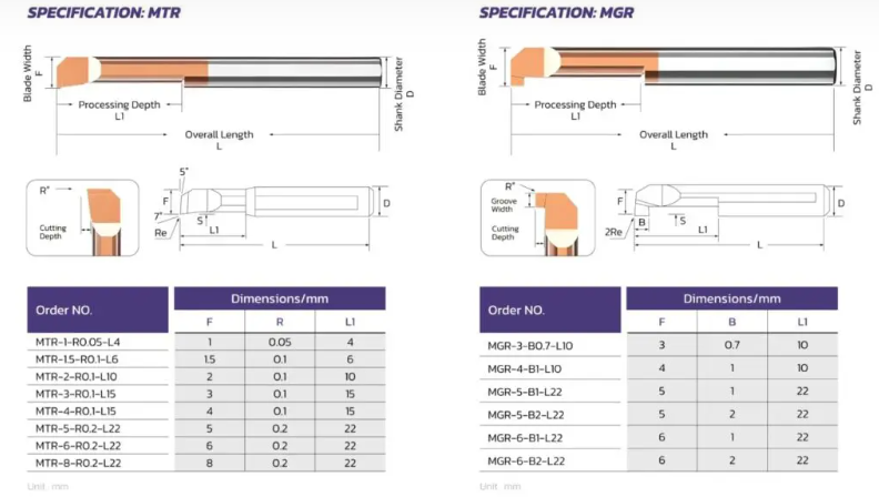
- The selection of internal hole machining tools follows these principles:
- Choose the largest possible boring bar diameter while ensuring sufficient chip clearance between the boring bar and the hole.
- Ensure compatibility with cutting parameters and chip shape for smooth chip evacuation.
- Choose the smallest possible overhang for the boring bar length. The clamping length should not be less than three times the boring bar diameter.
- Choose a primary clearance angle >75°, as close to 90° as possible, to direct cutting forces toward the boring bar.
- Select tools with a basic shape of a positive front angle and a positive front angle blade groove to minimize tool deflection.
- Choose a tool tip radius smaller than the cutting depth.
- Avoid vibration tendencies caused by insufficient tool engagement due to friction (not actual cutting action) during cutting or excessive tool engagement (large cutting depth and/or feed) leading to vibration through tool deflection.
- Choosing metal ceramic or thin-coated blades and non-coated blades can provide lower cutting forces, especially when the length-to-diameter ratio is large. Sharp cutting edges generally improve hole quality by minimizing vibration tendencies.
- Slot shapes with open chip breakers are more favorable for boring.
- In some cases, higher-strength blade grades may be needed to address chip clogging or vibration tendencies. Improving chip shape can be considered by changing the tool path.


