
With HUANA extensive range of TNMG turning inserts and chipbreakers, everything is possible. We designed TNMG inserts of various forms, sizes, and thicknesses with the same purpose in mind: to increase productivity and tool life in your turning applications. This extensive range, which covers all material groups, enables you to meet your material removal rates, tool life, and surface quality objectives.
When selecting a HUANA TNMG turning insert, selecting the correct insert for the job is only half the battle. There are further procedures to take, such as selecting the best chip breaker and grading. If you intend to use a TNMG 16 04 08 insert, the first thing you should evaluate is whether you intend to use it for general turning, finishing, or roughing. It is vital to realise that the negative inserts are the most powerful. As a result, HUANA TNMG insert are the best choices for general turning and roughing applications. Because of their thickness and sturdy insert forms, they allow for deeper cut depths and greater feed rates. Positive inserts are always the greatest option for finishing work since they may generate reduced cutting forces. As a result, they can easily get away with minimal cut depths while also minimising vibration.
TNMG inserts are ISO turning inserts that are found in practically all CNC lathes. It is utilised for Profile Turning and other shaft turning applications. The insert has six cutting edges.
Models of TMNG Inserts
TNMG insert is the floorboard of indexable turning blades, which is the mainstream of modern metal cutting applications of products that are primarily used in metal cutting milling cutting cutting thread turning areas such as the material can be divided into the coating blade metal ceramic blade ceramic knife TNMG blade super-hard etc. Its characteristics are high efficiency and high wear resistance, with processing efficiency more than four times that of traditional welding blade alloy blades. As coating technology advances, the key technology of wear-resistant high temperature resistant breakthrough will further improve efficiency and reduce processing costs.
Tnmg 16 04 08 insert is a sort of turning insert that is commonly used with P type tool holders. The most commonly used types are TNMG160404 and TNMG16048. In addition, inch size tnmg inserts can be manufactured. For example, TNMG160404 and TNMG16048.
External and internal turning tools of the M, P, and D types. For example, PTJNR/L, MTJNR/L, and DTJNR/L. All of them are relevant to tnmg 16 04 08 inserts. Sharp cutting edge, quick processing, easy chip removal, top option for finishing and semi-finishing, high surface finishing
This TNMG Insert has a T shape with negative angles for quick machining and good stability. The inserts are available in three different sizes. Typically, the insert dimension is determined by the demands of the client and the available space in the application for the cutting tools. The stability will improve as the insert size increases. Customers can choose the appropriate dimension by taking into account the working conditions and the equipment. When compared to a standard welding blade, the processing efficiency of the TNMG 220404 Insert improves by more than four times. Furthermore, it has high efficiency, wear resistance, high temperature resistance, corrosion resistance, high stiffness, low prices, energy savings, and a long service life. The TNMG Insert is primarily utilised in metal turning, milling, cutting and grooving, thread turning, and other similar applications.
TNMG inserts are replaceable and typically indexable cemented TNMG 220404 bits used in the machining of steels, cast iron, high temperature alloys, and nonferrous materials. TNMG inserts provide quicker machining and better metal component finishing. TNMG 220404 inserts are more heat resistant than high speed steel tools.
TNMG inserts are made of a metal matrix composite in which TNMG particles serve as aggregates and a metallic binder acts as the matrix. Sintering is the process of mixing the TNMG particles with the binder. During this process, the binder will ultimately enter the liquid state, but the TNMG (which have a considerably higher melting point) will stay solid. The binder embeds/cements the tnmg 1604 carbide inserts, resulting in a metal matrix composite with specific material characteristics. The inherently ductile metal binder compensates for the TNMG nature, increasing toughness and durability. Such TNMG 1604 CARBIDE INSERTS properties, which are principally governed by grain size, cobalt concentration, dotation, and carbon content, can be greatly modified within the HUANA TNMG manufacturer’s domain of influence.
The TNMG turning insert features a triangular form with a 60-degree cutting angle, offering shock protection without reducing wear resistance for roughing to finishing of steel in tough to medium machining circumstances. This negative insert is double-sided and contains a chip groove on both sides, a hole in the middle, and six cutting edges. It has sharp edges and no clearance, making it a better alternative for exterior turning than a positive insert. TNMG grade with shock resistance without sacrificing wear resistance. This grade’s edge strength also makes it suited for interrupted cuts at high removal rates. Lower temperatures are used to deposit MTCVD coatings than CVD coatings. Lower temperatures prevent cracking in the coating and promote toughness and smoothness while restricting wear resistance..
Chipbreakers Of TNMG
The TM, MA, PM, and HQ are the several chipbreakers that are available for purchase with the TNMG. The TM and MA chipbreakers both provide fast cutting speeds and feed rates thanks to their respective designs. Both the PM and HQ chipbreakers are built for medium-duty machining applications. When more machining stability is required, the HQ chipbreaker should be used as the tool of choice. The MA chipbreaker is optimised for use with shallow cutting depths and relatively slow feed rates. This chipbreaker produces modest cutting forces and is thus appropriate for components with thin walls and slender shafts.
There is a tolerance of plus or minus 0.002 inches to 0.005 inches in the distance from the triangle’s base to its apex. The insert has a tolerance of + or – 0.002 inches to 0.005 inches in terms of its theoretical diameter. The thickness tolerance for the insert is + or – 0.005 inches. It is possible for different shapes and sizes of inserts to have varying inscribed circle (iC) measurements. These measurements are connected to the range of cutting depths, speeds, lead angle, and feed rates that an insert is capable of. The inscribed circle is the biggest circle that can be made within the confines of the insert form. It is also known as the circumscribed circle. In general, the maximum cutting depth will grow along with the insert size and iC when those two variables are increased. When utilising the insert, the cutting depth has an effect on the pace of metal removal, the number of cuts, the chip evacuation, and the amount of power that is required.
Turning, milling, drilling, and grooving are all examples of applications that can benefit from the use of TNMG inserts, which are tiny cutting tools designed to remove material in both exterior and internal cutting applications. They are kept in place by an insert holder, have a number of cutting edges, and may be rotated when one of the cutting edges becomes dull. One operation can yield a wide variety of cuts if many inserts are utilised in conjunction with each other. The rake angle, also known as the clearance angle, is the angle at which an insert clears a path through the material. An insert can either be positive or negative. Inserts are assigned a code based on the particular cutting and application capabilities they possess. Each individual component of the code denotes specific information on the insert, including its shape, nose angle, clearance, tolerance, size, geometry, grade, and chipbreaker type. HUANA is a manufacturer of tools that are used for milling, drilling, and turning.
Specifications:
| Insert Shape | Type | Dimension | ||||
| L | ΦI.C | S | Φd | r | ||
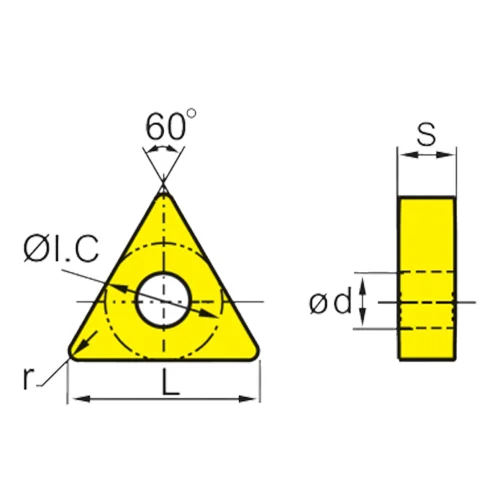 | TNMG160404 | 16.5 | 9.525 | 4.76 | 3.81 | 0.4 |
| TNMG160408 | 16.5 | 9.525 | 4.76 | 3.81 | 0.8 | |
| TNMG160412 | 16.5 | 9.525 | 4.76 | 3.81 | 1.2 | |
| TNMG160416 | 16.5 | 9.525 | 4.76 | 3.81 | 1.6 | |
| TNMG220408 | 22 | 12.7 | 4.76 | 5.16 | 0.8 | |
| TNMG220412 | 22 | 12.7 | 4.76 | 5.16 | 1.2 | |
| TNMG220416 | 22 | 12.7 | 4.76 | 5.16 | 1.6 | |
| TNMG270608 | 27.5 | 15.9 | 6.35 | 6.35 | 0.8 | |
| TNMG270612 | 27.5 | 15.9 | 6.35 | 6.35 | 1.2 | |
Chip Breaker:
| TM | CM | HQ | CQ | GS |
 |  |  |  |  |
| MA | MS | HA | HS | PR |
 |  |  |  |  |
| MQ | JMS | PM | R-S | L-S |
 |  |  |  |  |
How To Pick The Suitable TNMG Turning Insert?
When selecting a turning insert, there are a lot of different parameters to think about. In order to obtain effective chip control and machining performance, it is important to carefully pick the insert geometry, insert grade, insert shape (nose angle), insert size, nose radius, and entry (lead) angle.
- Choose the geometry of the insert according on the operation you’ve selected, such as completing.
- Choose the insert with the widest feasible nose angle for optimal strength and cost effectiveness.
- Determine the appropriate size of the insert based on the depth of the incision.
- For maximum insert strength, use the nose radius that is the biggest achievable.
- If there is a tendency for vibration, you should choose a nose radius that is smaller.
Turning insert geometry
Turning geometries may be broken down into three fundamental categories that are best suited for finishing, medium, and roughing operations, respectively. The diagram illustrates the working area for each shape based on the allowed chip breaking that can occur in relation to the feed rate and the depth of cut.
- Roughing
Combinations with a deep cutting depth and a rapid feed rate. operations that require the most cutting-edge level of security.
- Medium
Operations ranging from medium to mild roughing. A diverse selection of depth of cut and feed rate combinations are available.
- Finishing
The operations were performed with shallow depths of cut and slow feed rates. operations that need only a little amount of cutting force.
Changing the Wiper Geometry
- Wiper inserts can be used to increase surface finish with conventional cutting data or to maintain surface finish at significantly higher feed rates.
- The WMX wiper geometry is the initial choice and a suitable place to start for most applications. When circumstances change, there is always a viable option.
- In the event of vibration issues, use a positive wiper shape to reduce forces and retain productivity.
Choose the following wiper geometry:
-WL: For better chip control when switching to a lower fn/ap.
WF: Improves chip control while lowering the fn/ap. When vibrations occur, reduced cutting forces are also required.
WMX: The leading choice in the broad chip application field. Maximum productivity, adaptability, and finest outcomes are provided.
WR: When a stronger edge line is required, such as for interrupted cuts.
Turning Insert grade
The insert grade is largely determined by:
- Component substance (ISO P, M, K, N, S, H)
- Method classification (finishing, medium, roughing)
- Machining parameters (good, average, difficult)
- The insert geometry and grade compliment one another. For example, a grade’s toughness can compensate for a lack of strength in an insert geometry.
Changing the insert shape
The insert shape should be chosen in relation to the tool’s needed entry angle accessibility. To ensure insert strength and dependability, the maximum feasible nose angle should be chosen. This must be weighed against the variety of cuts that must be performed.
A large nose angle is powerful, but it demands more machine power and is more prone to vibration. A narrow nose angle is weaker and has a smaller cutting edge engagement, making it more vulnerable to the effects of heat.
Size of the TNMG turning insert
Choose the insert size based on the application requirements and the available area for the cutting tool. The stability improves with a greater insert size. Insert sizes larger than IC 25 mm are often used for severe machining (1 inch). When completing, the size may often be lowered.
How to Select Insert Size?
Ascertain the greatest depth of incision, ap
Determine the required cutting length, LE, while also taking into account the tool holder’s entrance (lead) angle, the depth of cut, ap, and the machine specification. The right cutting edge length, L, and IC for the insert may be chosen based on the required LE and ap.
Entering angle for turning
The angle formed by the cutting edge and the feed direction is known as the entrance angle, KAPR (or lead angle, PISR). For a successful turning operation, the right entering/lead angle must be chosen. The angle of entry/lead influences:
- The creation of chips
- Cutting force direction
- length of the cutting edge in the cut
- Large angle of entry (small lead angle)
- The forces are aimed at the chuck. There is less likelihood of vibration.
- Capability to rotate shoulders
- Higher cutting pressures, particularly near the cut’s entry and exit
- In HRSA and case-hardened workpieces, there is a tendency for notch wear.
- Small angle of entry (large lead angle)
- Increased radial forces exerted into the workpiece will result in vibration.
- decreased cutting edge load
- Produces a thinner chip, resulting in a greater feed rate.
- Cuts down on notch wear.
- A 90° shoulder cannot be turned.
Conclusion
Always choose a HUANA TNMG insert size based on the application’s unique demands and available cutting tool space. A rather large insert size improves stability. TNMG inserts are ISO turning inserts that are found in practically all CNC lathes. HUANA TNMG insert utilized for Profile Turning and other shaft turning applications. Always choose HUANA TNMG insert for any milling application.
