Why Flank Wear Matters More Than You Think
Flank wear—the progressive loss of material along the clearance face of a cutting tool—is the most common and most predictable wear mode you will see in day-to-day CNC operations. When managed correctly, it becomes your best indicator for scheduling tool changes, stabilizing surface finish, and preventing unexpected breakage. When ignored, it quietly increases cutting forces, heats the edge, elevates burrs, and can trigger a sudden cascade into chipping or edge fracture.
This article is a practical, picture-first field guide to flank wear. You will learn how to photograph it (macro and microscope), how to measure it consistently, how to link what you see on the edge to root causes in your process, and which levers—speed, feed, coolant, grade/geometry, rigidity—to move first. All examples are written for real production floors, not laboratory conditions.
What Exactly Is Flank Wear?
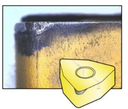
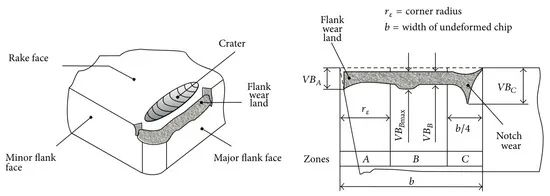
Flank wear appears as a relatively uniform, matte band on the clearance face just behind the cutting edge. It grows gradually with time-in-cut and is strongly correlated with the heat and friction at the chip–tool–work interface. Because the contact is on the clearance face, flank wear mostly tracks sliding abrasion and temperature rather than chip flow. In a healthy process, flank wear is your normal end-of-life (EOL) condition.
Why Flank Wear Happens: Mechanisms at Low vs. High Cutting Speeds
Flank wear has multiple contributing mechanisms. Which one dominates depends heavily on cutting speed (vc) and temperature at the edge:
- Low/Moderate vc: abrasion and micro-erosion dominate. Hard carbides or work-hardened particles in the workpiece act like sand, scoring the clearance face. Small patches of coating can be plucked away, exposing the binder; continued sliding weakens grain support.
- High vc: diffusion wear becomes more significant. Elevated temperatures accelerate atomic diffusion between the tool/coating and the work material, thinning the protective layer and deepening the wear land even when chips evacuate cleanly.
In practice, you will often see a mixed mechanism—abrasion defines the band and temperature accelerates its growth. The diagnostic value is that changing vc and coolant effectiveness often changes the slope of wear growth more than changing feed.
How to Photograph Flank Wear: Macro and Microscopic Checklists
High-quality images make the difference between guesswork and fast, confident decisions. Below are illustrative figures; replace them with your actual photos when ready.
- Magnification: 1×–10× (a phone with clip-on macro lens is sufficient).
- Lighting: two off-axis LED sources at ~45°; avoid on-axis glare that hides the wear band.
- Angles: rake face at 30–45°, clearance face at 30–45°, true edge-on profile to show band width and edge integrity.
- Background: matte black or light gray; fix white balance at 5000–6500 K across all shots.
- Include a scale: a 1 mm or 0.5 mm rule in frame for later measurement.
4.2 Microscopic Photography
- Instrument: reflected-light metallurgical or digital microscope.
- Magnification set: 50×, 200×, 500× (standard capture stack).
- Illumination: ring light plus one oblique fiber to reveal topography; use focus stacking if available.
- Calibration: capture a 10 μm/div grating once per session; keep files in a labeled folder by lot/heat.
Measuring Flank Wear the Same Way Every Time
Consistency beats precision for shop-floor control. Use the same magnification, a fixed measurement line, and the same end-of-life thresholds. Record VBmax (the maximum wear-band width) and, if possible, VBavg across a representative segment of edge. Add part Ra/Rz and a short free-text note.
Table 1. Practical VB stop-rules by operation (adjust for part tolerance and finish requirements).
Operation | Primary EOL (VB) | Secondary Stop Rule | Notes |
OD/ID Turning – Finish | VBmax ≤ 0.15 mm | Surface Ra > 1.6 μm or burr height > 0.10 mm | Keep sharp edge/hone small; stabilize coolant aim. |
OD/ID Turning – Rough | VBmax ≤ 0.30 mm | Edge notch visible or chip control degrades | Prefer tougher grade/edge prep. |
Face Milling – Finish | VBavg ≤ 0.08 mm | Finish scatter increases or burr grows | Balance tooth count and feed per tooth. |
Face Milling – Rough | VBavg ≤ 0.20 mm | Chatter or chip packing appears | Improve rigidity; check axial rake/chip-breaker. |
Drilling – Carbide | Margin wear ≤ 0.15 mm | Hole drift > IT10 or unacceptable exit burr | Ensure coolant-through; avoid dwell. |
From Symptom to Cause to Action
Table 2. Diagnostic matrix focused on clearance-face wear.
What you see | Likely dominant cause | Change these first |
Uniform, slow-growing VB band | Normal abrasion with adequate temperature control | Stay in window; consider slightly harder, wear-resistant grade for longer life. |
VB growing too fast at low vc | Abrasive inclusions/work-hardened skin; insufficient coolant effectiveness | Increase coolant concentration/aim; try a harder coating; cautiously raise vc to reduce BUE. |
VB growing too fast at high vc | Diffusion wear due to excessive temperature | Reduce vc 10–20%; improve through-tool/flood aim; pick diffusion-resistant coating. |
Pronounced notch at entry/exit | Oxidation or scale at the surface; dry entry; intermittent contact | Add lead-in or pre-face; increase entry coolant; tougher grade/edge prep. |
VB with random micro-chips | Vibration/rigidity limits superimposed on VB | Shorten overhang; improve fixturing; increase edge hone/T-land; adjust feed at entry/exit. |
Baseline Cutting Data Windows (Illustrative)
Use these as starting points and tune with the diagnostic matrix above.
Material | Operation | vc (m/min) | f (mm/rev or mm/tooth) | ap (mm) | Notes |
1045 (HB ~200) | Turn – Finish | 200–300 | 0.10–0.20 | 0.5–1.5 | If BUE appears, raise vc or sharpen edge. |
1045 (HB ~200) | Turn – Rough | 180–260 | 0.25–0.40 | 2–4 | If crater wear appears, reduce vc and improve coolant aim. |
17-4PH (H900) | Face Mill Ø63 – 6F | 120–180 | 0.05–0.10/tooth | 0.5–1.0 | Prefer through-tool coolant; avoid dwell. |
6061-T6 | Face Mill Ø80 – 8F | 600–900 | 0.08–0.18/tooth | 0.5–2.0 | Use polished rake; eliminate BUE. |
Inconel 718 | Turn – Rough | 30–60 | 0.15–0.30 | 1–3 | Maximize rigidity; avoid interruption/dwell. |
Coolant Strategy: The Cheapest Way to Slow VB
- Raise concentration within supplier limits when VB accelerates; low concentration promotes adhesion and abrasive pluck-out.
- Aim at the chip–tool contact, not just the general zone; reposition nozzles after each setup change.
- Prefer through-tool or high-pressure lines on difficult alloys; avoid on/off shock that spikes thermal cycling.
- Track °Brix or refractive index weekly; document changes alongside tool-life charts.
Rigidity and Entry Conditions
Flank wear rates compound quickly when vibration is present. Reduce overhang, stiffen the workholding, and stabilize entry/exit. Even for a VB-dominated failure, a cleaner entry (ramp-in, small lead-in chamfer, or soft-start feed) prevents micro-chips that otherwise seed accelerated wear along the band.
Example: Stabilizing VB on 4140 with Simple Changes
Part: 42CrMo4 (AISI 4140) QT, 30 HRC | Tool: HUANA CNMG12.. P25, 0.4 mm hone, TiAlN | Setup: 3-jaw + tailstock, overhang 2.0×D | Coolant: 7% semi-synthetic, flood
Initial cut: vc 180 m/min, f 0.28 mm/rev, ap 2.5 mm. At 8 minutes, VBmax ~0.22 mm with scattered entry micro-chips; surface Ra 3.0 μm; minor exit notch.
Changes, one at a time:
- Shortened overhang to 1.6×D and added a steady rest.
- Retained geometry but increased edge T-land width slightly (stronger edge).
- Raised vc to 200 m/min to suppress BUE and move out of a chatter band.
- Added 8–10° lead-in ramp to soften entry load; retargeted coolant at the edge.
Result: at 12 minutes VBmax ~0.18 mm with no new chips; Ra 1.4 μm and burr height halved. The life-per-edge increased with more stable finish and fewer unpredictable stops.
A Five-Step VB Control Workflow
- Detect & tag: when a counter or finish trigger hits, capture macro shots (rake/clearance/edge) + one 200× micro.
- Classify: confirm the mode is VB-dominated and note any notch or micro-chipping.
- Decide: apply the diagnostic matrix—adjust vc/coolant first for diffusion/abrasion; rigidity/entry for chips.
- Document: record VBmax/VBavg, Ra/Rz, part count/time-in-cut, coolant °Brix, notes.
- Review weekly: plot VB vs. minutes/parts; verify slope improves after changes.
Conclusion: Make Flank Wear Predictable
Flank wear is not the enemy—unpredictability is. With disciplined photography, standardized VB measurements, and a short list of root-cause levers, you can turn an inevitable wear process into a predictable, controllable, and more profitable one. Replace the guesswork with photos, tables, and a weekly review, and your shop will see longer tool life, steadier finish, and fewer surprises.