In precision machining, parting and grooving operations may look simple — but tool selection can make or break your productivity. The right cutting tool not only ensures clean, burr-free cuts but also extends tool life and minimizes machine downtime.
If you’ve ever faced tool breakage, chatter, or inconsistent surface finishes when parting small components, this guide is for you. Let’s go through four essential steps to help you choose the perfect cutting tool for your next job.
Step 1: Check the Tool Shank Size and Machine Compatibility
Before anything else, you must confirm that the toolholder and machine interface match.
The tool shank size must correspond to your CNC lathe’s turret slot or tool post design.
Every machine model — whether Swiss-type, multi-axis, or standard CNC lathe — has its own interface specification.
Why It Matters
A mismatch in shank size can cause:
Misalignment during setup
Vibration during cutting
Poor repeatability
Also, check the workpiece diameter and cutting path clearance. Ensure that the insert and holder can cut without interference between the tool, chuck, and workpiece.
Tip from the Experts:
Always verify with your machine’s technical manual. Toolholder rigidity is the foundation of smooth and chatter-free parting.
Step 2: Choose the Correct Toolholder (R/L Direction and Neck Type)
When it comes to toolholders, orientation is critical. You’ll typically find right-hand and left-hand toolholders — each designed for specific cutting directions.
How to Decide
Right-hand holders are the standard for most setups.
Left-hand holders are used when:
The workpiece is too short to be clamped securely by the sub-spindle.
You’re using a Swiss-type lathe that rotates in the opposite direction.
Choosing the correct orientation prevents tool collision and enables efficient chip evacuation.
Long-Neck Toolholders for Tight Spaces
A long-neck toolholder helps avoid interference between the chuck and the toolholder, allowing machining closer to the guide bushing.
This type is ideal for small parts or low-rigidity workpieces, ensuring stability and precision during cutoff.
Step 3: Select the Right Insert Geometry
Once you’ve chosen your holder, it’s time to select the insert.
Insert geometry determines chip flow, cutting resistance, and surface quality.
Two Main Types of Inserts:
Positive-rake inserts
Neutral (zero-rake) inserts
Let’s look at how they differ.
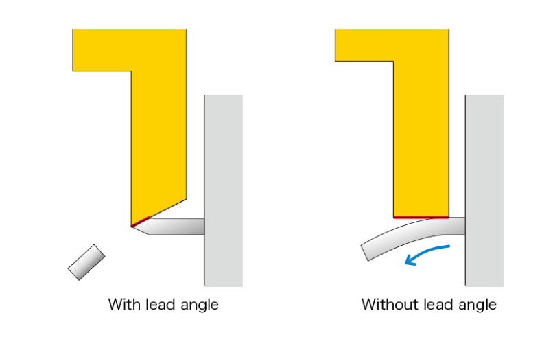
Positive-Rake Inserts
These inserts have a sloped cutting edge, which reduces cutting forces.
They’re ideal for small-diameter parts, fine finishing, and operations without a sub-spindle.
Advantages:
Lower cutting resistance
Reduced workpiece deflection
Smoother surface finish
Note: Because of their rake angle, chips may not flow straight, potentially affecting the part end face.
Neutral-Rake Inserts
Neutral inserts feature a flat cutting edge.
They’re stronger and provide stable performance for harder materials or continuous cuts.
Advantages:
Greater cutting-edge strength
Straight chip evacuation minimizes end-face damage
Even tool wear and longer life
Neutral inserts are perfect for rigid setups and cast iron or steel parts that generate high cutting loads.
Table: Comparison of Positive vs Neutral Rake Inserts
Feature | Positive-Rake Insert | Neutral-Rake Insert |
Cutting Force | Low | High |
Edge Strength | Moderate | Strong |
Surface Finish | Excellent | Good |
Chip Flow | Curved | Straight |
Best for | Small parts, light cuts | Hard materials, stable setups |
Tool Life | Medium to long | Long |
Workpiece Deflection | Minimal | Slightly higher |
By understanding this difference, you can pick the right insert to balance cutting speed, finish, and stability.
Step 4: Determine the Correct Cut-Off Width
The final step — and often the most overlooked — is selecting the appropriate cut-off width.
Insert Image: Cross Section Showing Cut Width and Workpiece Diameter
As the workpiece diameter increases, the cutting load rises sharply.
To maintain tool rigidity and prevent insert breakage, increase the insert width proportionally.
Recommended Guideline:
The ideal cut-off width is approximately 10% of the workpiece diameter.
Example:
For a 20 mm diameter bar, use a 2 mm-wide insert.
For a 50 mm bar, use around 5 mm.
Proper width selection ensures balanced strength and efficient chip evacuation.
Common Problems and How the Right Tool Solves Them
Even experienced machinists encounter challenges in parting and grooving operations.
Here’s how proper tool selection can prevent costly issues:
Problem | Cause | Solution |
Tool chipping or breakage | Excessive cutting load | Choose wider insert or stronger neutral rake |
Poor surface finish | Wrong rake geometry | Use positive-rake insert for smoother results |
Chips wrapping around workpiece | Incorrect chip flow | Optimize rake angle and coolant direction |
Workpiece bending | Low rigidity | Use long-neck holder with better support |
Pro Tips for Optimal Performance
✅ Check rigidity first – Always ensure toolholder and setup stiffness before increasing cutting speed.
✅ Use proper feed rates – Too low feed can cause rubbing and premature wear.
✅ Monitor tool wear – Replace inserts early to prevent breakage and protect your part.
✅ Avoid vibration – Minimize overhang and use anti-vibration holders if needed.
✅ Keep chips clear – Use high-pressure coolant or air blow for deep or narrow cuts.
Why Tool Selection Matters in Modern Manufacturing
In an era of automation and precision, cutting tool optimization directly impacts production cost, surface quality, and machine utilization.
Choosing the right parting tool:
Reduces downtime by extending tool life
Improves finish, reducing secondary operations
Increases cutting speeds, improving cycle time
Enhances consistency across large production runs
A small change in insert geometry or holder design can yield massive efficiency gains.
Real-World Example
A precision automotive parts supplier switched from standard carbide inserts to optimized positive-rake ceramic inserts from Huana Tools for aluminum and stainless parting operations.
The results were impressive:
Tool life improved by 40%
Surface roughness reduced by 30%
Total machining cost per part decreased by 18%
This simple tooling upgrade transformed their productivity and helped them meet delivery deadlines.
Partner with Huana Tools for Smarter Tool Selection
At Huana Tools, we believe the right tool choice begins with understanding your process.
We provide cutting-edge parting and grooving solutions backed by years of experience in CNC machining and tool engineering.
Our Advantages:
Precision-engineered inserts for both positive and neutral geometries
Toolholders designed to minimize vibration and ensure rigid performance
Expert recommendations for your specific material and machine type
Competitive pricing for OEM and distributor partnerships
Whether you’re working with stainless steel, cast iron, or non-ferrous alloys, our experts can help you select the perfect combination of insert and holder to boost productivity and quality.
Conclusion
Selecting the best cutting tool may seem like a small detail — but it determines whether your machining line runs smoothly or struggles with downtime and scrap.